From device setup to daily inspection
Configure the station, check string status, investigate faults and export operating records.
01 First use
- Create a projectCreate or open a project and save it somewhere easy to back up.
- Connect devicesConfigure channels, add devices, and check current, voltage and sample times.
- Organize the stationCreate arrays, assign inverters, and configure policies and environmental data.
- Start inspectingSave the project, review monitoring status and faults, and export reports.
| Prepare | What to check |
|---|---|
| Communication details | Device protocol, address, serial or network settings, and a point list or suitable template. |
| Site information | Array and inverter names, actual PV input counts, MPPT wiring, module specifications and orientation. |
| Permissions | Configuration requires administrator access. The license also limits which objects you can access. |
For daily viewing, start at Monitor → PV health monitoring. The question mark beside a parameter explains its purpose, range and required input.
02 Projects and device setup
Open: Project; Configuration → Device data
- Create or open a project from the Project menu. Save a new project before continuing.
- Open Device data, right-click an empty area of the device tree to add a channel, and enter its serial or network settings.
- Right-click the channel to add a device, or scan for devices if the protocol supports scanning. Enter the actual device address.
- Select a device, import a matching template or configure its points, and verify addresses, data types, scaling and units.
- Right-click the channel to connect. Check that the device is online and that current, voltage and sample times keep updating.
- Enable history recording for the required points if you need historical curves, then save the project.
| Check | What to do |
|---|---|
| Device template | Use a template matching the model, protocol version and PV input count. Check every item after importing, especially the string assignments. |
| Electrical measurements | Confirm that current is in A and voltage is in V. Incorrect scaling affects power readings and detection results. |
| String points | Prefer a template matching the site model and PV input count. For manual setup, use the device point list to verify each string's current, voltage and assignment. Ask the device or template provider if you cannot confirm them. |
| Saving and backups | Save updates the current project; Save as writes another file. Include the history records in the data directory when backing up. |
Save as retains the project's identity and history association. Create a new project for an independent station. Do not use total device DC current or voltage as the measurements for every string.
03 Arrays and strings
Open: Monitor → PV health monitoring
| Task | How to do it |
|---|---|
| Create an array | Right-click an empty area of the monitoring canvas, choose Add array, and enter a name. |
| Assign inverters | Right-click an array → Device management, select devices and confirm. Devices you deselect return to Unassigned. |
| Change membership or order | Administrators can drag an inverter to another array or reorder arrays. Save the project afterward. |
| View details | Double-click an array to see its inverters, then an inverter to see its strings. Use the page's back control to return to the parent view. |
| Temporarily stop checking a string | Right-click a string and choose Ignore; choose Restore when it should be checked again. Valid measurements remain visible while it is ignored. |
Removing a device from an array retains its settings and history. Changing comparison groups or point assignments may restart learning for affected strings. Check the actual wiring before making changes.
04 Daily monitoring
Open: Monitor → PV health monitoring → Overview. Use the header to switch between Overview, Cards and Topology.
Overview: start with status, then review trends
| Area | What to look for |
|---|---|
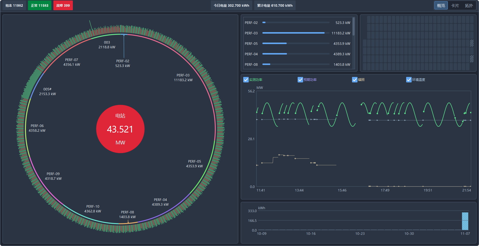
| Header status and energy | Read the string total and counts by status for the current scope. At station scope, today’s and total energy appear in the middle, in kWh. |
| String status ring | The center shows measured DC power for the current scope, with sectors for arrays, devices or MPPTs. Colors indicate status and line lengths reflect power; hover for object and measurement details. |
| Power comparison and status calendar | Compare power among the objects within the current scope and review daily status over the last six months. Hover for values, dates and data completeness. |
| Daily power trends | Toggle the measured power, expected power, irradiance and ambient temperature legends. Move the pointer over the chart to inspect readings at a given time. Compare environmental changes using their legend values and their own units. |
| Generation over the last 30 days | At station scope, the lower chart shows daily energy. Hover for the date, energy and recording status. Without a configured meter, the chart remains visible and shows No collected data. |
Double-click an array or device sector to drill down; double-click the ring center to return to its parent. Header statistics and charts follow the current scope. Switch to Cards or Topology for detailed string measurements or device operations.
Daily inspection sequence
- Review the overviewIdentify arrays with faults or insufficient data first.
- Check the deviceOpen the inverter and verify its connection and latest samples.
- Check the stringReview current, voltage, power, detection status and learning status.
- Review recordsOpen fault details and related curves before arranging a site inspection.
| Status | What it means | Next step |
|---|---|---|
| Normal | No fault has been confirmed by the checks currently able to run. | Continue observing, including detection conditions and learning progress. |
| Fault | A detection fault has been confirmed. | Review its type, time and evidence, then inspect the site. |
| Warning | A condition needs attention. | Review data quality, curves and site conditions. |
| Unknown / insufficient data | Communication, points or detection conditions are not ready. | Investigate the specific reason shown on the page. |
| Ignored | Detection is paused for this string. Valid measurements remain available. | Check why it was excluded and restore checking after the site issue is resolved. |
Learning does not mean a fault. Learning complete does not mean every detection condition is ready. A value of -- means unavailable; check for missing, stale or unsynchronized data instead of treating it as zero.
05 Detection policies and comparison groups
Open: Configuration → Detection policy, or the detection policy entry in an array or inverter's context menu
- Choose a parameter category, then open the station, array or inverter. In the complete policy window opened from a device's context menu, Comparison groups and Device state mappings are listed on the left under Thresholds.
- Check the effective scope. Select Inherit parent to follow the parent configuration; clear it for independent settings.
- Select the checks and configure their thresholds, sampling and confirmation settings. Use the question mark beside a parameter for input requirements.
- In Comparison groups, drag strings with similar orientation, specifications and sunlight into the same group.
- Open the following Device state mappings tab. Double-click the station, array or inverter to configure its status rules. Child objects can inherit or use independent rules.
- OK saves the edits from all tabs together; Cancel discards them. Then save the project and return to monitoring to check the policy source and learning progress.
| Task | Key points |
|---|---|
| Copy parameters in bulk | Use Ctrl or a selection box to select objects on the policy canvas. Right-click the source object, copy the current parameter category, and check the target scope. |
| Select multiple strings | Use Ctrl for multiple selections, Shift for a range, or a selection box. Drag the selected strings into the target group together. |
| Ungrouped | These strings still belong to the default comparison group and participate in comparisons. Use Ignore if you want to stop checking a string. |
| Comparison groups and MPPT | Comparison groups identify comparable strings. MPPT mappings must match the actual electrical wiring. Check them separately. |
| Device state mappings | Mappings inherit from station to array to inverter. Select multiple objects and use the context menu to copy the source's mappings or restore inheritance. Read-only users can view them. |
Select the required checks in Detection items before configuring their parameters. Reverse-current checking requires signed current readings; group voltage and power checks require complete voltage data. Learned asymmetry requires valid learning first. MPPT deviation is for observation and is not an alarm switch.
Parameter guides: Basic parameters · Detection thresholds · Learned asymmetry · Comparison groups · Device state mappings · MPPT settings
Basic parameters: reference current, sampling and confirmation
| Parameter (default) | When to configure it | How to set it |
|---|---|---|
| Minimum generating reference current (1 A) | At dawn, dusk or in weak sunlight, normal generation may be hard to distinguish from standby current. | Set this using normal generating current and standby noise at the site. It checks generating conditions; configure zero-current and low-current thresholds separately. |
| Minimum generating reference strings (including target, 1) | A group contains several strings and you want enough normally generating strings available before comparison. | Use the actual number of usable strings in the group; do not exceed the reference count normally available. Provide at least two strings with comparable conditions for group comparisons. Check grouping and samples first if references are insufficient. |
| Fault/recovery confirmation (60 s) | Short cloud shadows or site fluctuations cause frequent fault and recovery changes. | Increase the duration for frequent short fluctuations. Shorten it for faster confirmation only after checking sample continuity. The same duration applies to faults and recovery. |
| Data freshness (120 s) | The normal communication update interval does not match the default freshness period. | Set it slightly longer than the normal update interval, with some margin. Investigate communication first if readings often expire; do not hide missing samples with a very long freshness period. |
| Maximum sample time skew (30 s) | Current, voltage or other readings in the group update at different times. | Set the acceptable difference between normal sample times. It must not exceed data freshness. Try to synchronize related points before relaxing this limit. |
| Maximum sample gap during confirmation (120 s) | Confirmation is repeatedly interrupted by sampling gaps, or you need to limit long gaps. | Allow the normal update interval. The value must be at least the station detection interval and no greater than data freshness. Resolve communication and sampling issues before accepting long gaps. |
Detection items: threshold settings
| Parameter (default) | When to configure it | How to set it |
|---|---|---|
| Zero current: zero-current threshold (0.05 A) | You need to find strings with almost no current while comparable strings are generating normally in daylight. | Check zero-point noise and measurement resolution, then choose a small value near zero. It must not exceed the minimum generating reference current. Do not raise the threshold instead of investigating an open circuit or wiring issue. |
| Low current: threshold relative to reference (50%) | You need to identify current that stays below the group's normal level. | First ensure comparable orientation, modules and sunlight. Set the acceptable low-current level: a higher percentage flags low current more readily; a lower one is more tolerant. Enter 50 for 50%, not 0.5. |
| Voltage out of range: minimum 100 V, maximum 1500 V | You need to check whether string voltage is outside the site's permitted operating range. | Set both limits using the string's series module count, device specifications and permitted operating range. Minimum must be less than maximum. Check strings with different specifications separately. |
| Reverse current: magnitude threshold (0.05 A) | The point correctly reports positive and negative current, and you need reverse-current checking. | Verify polarity and scaling first. Enter a positive magnitude based on permitted reverse current and zero-point noise; do not enter a negative value. |
| Current imbalance: deviation (20%) | Strings under similar conditions show persistent differences in current. | Check comparison-group membership first. Reduce the percentage for greater sensitivity. Increase it only after confirming that the larger difference is normal for the site. |
| Reference-group voltage deviation (15%) | Strings with the same specifications and series module count should have similar voltages, and you need to identify deviations. | Compare only strings with similar voltage conditions. Smaller values are more sensitive. If series module counts differ, change the groups rather than simply relaxing the threshold. |
| Low power within comparison group: threshold relative to reference (80%) | Current and voltage are complete and synchronized, and you need to identify persistently low power within a group. | Check point units and grouping first. A higher percentage flags low power more readily; a lower one is more tolerant. Configure missing voltage points before using this check. |
Learned asymmetry: learning and recovery settings
| Parameter (default) | When to configure it | How to set it |
|---|---|---|
| Minimum valid learning days per pair (7 days) | You need to adjust how many valid learning days are required before use. | Normally keep the default. Adjust it using continued site observations when needed. If learning is waiting, check valid-day progress and the displayed reason. |
| Minimum valid half-hour windows per pair (48) | You need more valid observations, or site data has not yet met the learning requirements. | Normally keep the default. Check the displayed learning progress and resolve missing data, grouping or environmental issues first. |
| Pair asymmetry deviation (20%) | Learning is complete and you need to identify persistent asymmetry relative to normal conditions. | If an acceptable normal difference causes too many warnings, check site conditions and learning status before increasing the threshold. Reduce it for greater sensitivity. |
| Recovery threshold relative to warning (60%) | Warnings reappear soon after recovery and you want more stable recovery status. | A lower percentage requires a fuller recovery before clearing a warning; a higher one allows earlier recovery. Start with the default and adjust after continued observation. |
| Minimum valid coverage per half-hour window (300 s) | Samples are sparse, or you want to accept only learning periods with more complete data. | Normally keep the default. Check the sampling interval and missing-data causes before changing it. Increase it when more complete learning data is needed. |
| Maximum ratio scatter allowed for learning (10%) | Changing weather or shading causes prolonged learning waits or unstable normal data. | Normally keep the default. A smaller value requires steadier data. Do not relax it just to speed up learning; first check site conditions and group comparable strings together. |
Configure the detection interval in Configuration → Station parameters (default 5 s, range 1–15 s). All devices use it. The maximum sample gap during confirmation must be at least this interval. If a change conflicts with child settings, check the independent array and inverter settings.
Comparison groups: group by site conditions
| Parameter (default) | When to configure it | How to set it |
|---|---|---|
| Add group, group name and string membership | Orientation, module specifications, series counts or sunlight differ, making direct comparison unsuitable. | Create and name groups by site conditions, then drag the corresponding PV strings into them. Use names recognizable at the site. Keep enough comparable strings together rather than giving every string its own group. |
| Ungrouped | New strings have not yet been placed in a named comparison group. | Ungrouped strings still participate in the default group. Use Ignore to exclude a string; Ungrouped does not stop checking it. |
| PV input count (station and array templates) | You are preparing groups for several devices with the same wiring. | Enter the actual PV input count of the applicable devices, then assign each input to a group. Check input counts and order before applying. Configure devices with different counts separately. |
Device state mappings: follow the device manual
| Parameter (default) | When to configure it | How to set it |
|---|---|---|
| Device data | The device provides operating, fault or warning status points that you want to use for its status display. | On a device page, double-click to select one of its points. For a station or array, enter the applicable point ID. Share parent rules only when that ID has the same meaning on every applicable device. |
| Match mode: numeric/enumerated equality; match value | The device manual specifies an individual status value or text. | Enter the specified number or complete text, such as status value 768. No upper bound is required. Check the point's actual displayed value first. |
| Match mode: numeric range; lower and upper bounds | The device manual defines a continuous numeric range as one status. | Enter valid numbers with lower bound no greater than upper bound. Both endpoints are included. Only this mode requires an upper bound. |
| Match mode: bitmask; mask | The device manual explicitly defines fault or warning status bits. | Use the specified nonzero integer mask in decimal or hexadecimal with a 0x prefix, such as 1 or 0x04. Any specified bit may trigger a match. Do not guess bit values. No upper bound is required. |
| Status: normal, fault or warning | You need to specify what a matching rule means. | Choose according to the device's status definitions. Check actual point values after adding or removing rules, then confirm. For an independent configuration with no rules, clear inheritance and empty the list. Select inheritance to keep following the parent. |
Missing samples or long periods without new data can leave confirmation and learning waiting. Check communication and sampling first instead of relaxing freshness or confirmation settings merely to remove the waiting message.
06 Station and environmental data
Open: Configuration → Station parameters; Configuration → Environmental data
- In Station parameters, enter the location, valid coordinates and ground albedo, and set the detection interval (1–15 s, default 5 s).
- Open Environmental data and choose online weather or site environmental points as the current source.
- Finish the source configuration and check preview values, units, sample times and quality status.
- Enable learning assistance or daily irradiance/power diagnostics as needed, confirm and save the project.
| Source | Setup | Points to check |
|---|---|---|
| Online weather | Enter station coordinates first, then configure the source and request settings. Enable it after a successful preview. | Requires a network connection. Check the service's applicable conditions. Model data is not the same as site measurements. |
| Site environmental points | Select each device, point and input unit, and verify irradiance, ambient temperature and other readings. | Check assignments and units. If data is stale or invalid, investigate sensors and communication first. |
Environmental data uses the currently selected source. A site-source failure does not automatically switch to online data. Check previews and diagnostics again after changing sources.
Meter configuration and energy readings
- First connect the meter in Device data and verify its generation-direction AC active-power and energy points. An administrator can right-click the device in the monitoring view, choose Mark as meter, then open Meter measurements.
- Select distinct power and energy points and their input units. Choose the actual register type: Meter daily generation or Meter cumulative generation. Units must match values after acquisition scaling.
- Check the stale-data limit and allowed sample skew. To use this meter for station energy, select Use as the station meter, confirm and save the project. The station uses one selected meter; verify its scope before replacing the source.
Today’s energy is the energy recorded for the current day; total energy uses a valid cumulative-register reading. With only a daily register, total energy shows --. Energy is not estimated from the overview power chart.
If energy records are incomplete, readings are missing around midnight, or the meter resets or rolls back, review chart messages, the meter and historical records. Environmental devices and meters can belong to arrays; use the relevant inverter points for string monitoring.
07 MPPT deviation
Configure: Configuration → Detection policy → MPPT deviation; view inverter details or Function → Operational diagnostics
- Module parametersFor each string, enter the series module count and the Vmp and Imp of one module.
- InstallationEnter actual tilt and azimuth, and verify shared station parameters.
- MPPT mappingSet the channel count and connect PV inputs to MPPT channels according to the wiring.
- Review deviationCheck actual power, expected power and deviation. Read the reason if a value is unavailable.
| Displayed value | How to use it |
|---|---|
| Actual power | View the selected MPPT channel's actual power and verify its points and wiring. |
| Expected power | An estimated reference for reviewing power differences. Verify module specifications, installation settings and environmental inputs before use. |
| Deviation | Negative means actual power is below expected power; positive means it is above. Review shading, weather and power limiting at the site. |
MPPT settings: follow module specifications and wiring
| Parameter (default) | When to configure it | How to set it |
|---|---|---|
| PV selection, Select all and bulk entry | Several strings use the same modules and installation conditions. | Select the PV inputs you intend to edit first. Apply values together only to inputs with the same conditions. Select different inputs separately so one specification does not overwrite every string. |
| Series module count | You are adding a string, changing wiring or replacing modules. | Enter the actual number of modules in series on this string, not the device's total module count or the number of parallel branches. |
| Single-module maximum-power-point Vmp and Imp | Initial setup or a change of module model. | Enter Vmp (V) and Imp (A) from one module's STC specifications. Do not enter whole-string voltage, total device current, open-circuit voltage Voc or short-circuit current Isc. |
| Tilt | The installed module plane differs between strings. | Enter the angle relative to horizontal: 0° is horizontal and 90° is vertical. |
| Azimuth | Module orientation differs between strings. | Use the actual orientation: north 0°, east 90°, south 180° and west 270°. |
| PV input count and MPPT channel count | You are configuring a station or array template, or changing actual device MPPT wiring. | The template's PV input count must match its intended devices. Enter the actual number of independent MPPT channels; do not substitute the PV input count. |
| PV-to-MPPT mapping | Several PV inputs share an MPPT channel, or site wiring has changed. | Connect PV inputs to MPPT channels on the mapping page according to the actual wiring. Check the wiring diagram if uncertain. Reference-group numbers and MPPT numbers are separate and are not interchangeable. |
Set location, coordinates and ground albedo in Station parameters. Configure the environmental source in Environmental data. If MPPT data is incomplete, obtain the actual specifications rather than entering arbitrary values to remove missing-data messages.
MPPT deviation is for observation; a large deviation alone does not create a fault or warning. Ignoring a string pauses its detection without changing the wiring configuration or MPPT measurements shown.
08 Faults and warnings
Open: Function → Fault/warning history; monitored objects also provide related records in their context menus
- Find the recordFilter by array, inverter, status, detection item and time. Choose Today, Last 7 Days, Last 1 Month or Last 3 Months. Select Custom or click either time to edit dates, hours, minutes and seconds in the dual-calendar dialog.
- Review evidenceCheck the detection type, sample times, values and related curves.
- Arrange actionAcknowledge, assign, add notes and inspect the site as needed.
- Follow upRecord the outcome and continue observing recovery and the reason the record ended.
| Distinguish | What to do |
|---|---|
| Work marked complete | After recording maintenance progress, still check whether detection has recovered. Manual handling and detected recovery are confirmed separately. |
| Ended after a configuration change | Disabling a check, ignoring a string or changing its configuration may end an old record. Review the ending reason rather than assuming natural recovery at the site. |
| Communication or data interruption | Restore valid samples first. An existing active fault does not recover merely because communication is lost. |
Detection messages assist investigation. Confirm the device and string identity before acting. Follow site procedures for electrical inspections.
09 History, diagnostics and reports
| Open | Steps | Points to check |
|---|---|---|
| Monitor → History | Select the device and points → set start and end times → query → review data or curves. | History recording must be enabled beforehand. The default interval is 60 seconds. Data missing before recording was enabled is not filled in automatically. |
| Function → Operational diagnostics | Review sample times, data age, evaluable counts and waiting reasons. Use the tabs for daily diagnostics and MPPT indicators. | Resolve stale samples, missing mappings or storage errors before assessing faults. |
| Function → Station operation report | Choose a daily or weekly report and date → query → check data coverage → export CSV or PDF. | -- means usable observations are missing. Fault durations may overlap and should not simply be added together. |
| Daily irradiance/power diagnostics | Enable the required environmental source and diagnostic conditions, then review dates, coverage, baseline and deviation in Operational diagnostics. | Requires sufficient valid data and a baseline. Read waiting or unavailable reasons first. |
Verify the station, objects and time range before exporting. Back up history and monitoring data with the project, to a location separate from the operating directory.
10 System, tools and Web
| Open | Basic use |
|---|---|
| Monitor → System | View the system dashboard. Administrators can enter edit mode from the context menu, configure pages and components, then leave edit mode and save the project. |
| Monitor → Control | Review configured control flows. Verify targets and actions before changing a flow or sending control commands. |
| Tools menu | Open communication statistics, message display, communication tests or utilities as needed to investigate connections and samples. |
| Configuration → MQTT | Set the server, authentication and forwarded content as required. Save and check the connection status. |
| Configuration → EdgeWeb | Enable the service, configure its listening address, access token and page directory, and save. Open the actual configured address in a browser. |
EdgeWeb provides device, PV monitoring, history and fault views. Access depends on the token and current project permissions. Closing SolThings also stops the Web service.
Communication tests, writes and control commands can change site device status. Verify the device address, command and parameters before sending. Do not send arbitrary test writes to operating devices.
11 Licensing and preferences
| Open | Steps |
|---|---|
| Help → License management | Review the license status, copy the machine code using the provided control, give it to the license provider, then import a license file issued for this machine. |
| Configuration → User management | Switch to a user with the required permissions before configuration or maintenance work. |
| Configuration → Options | Set language, theme, global font and startup page, then confirm. Menu fonts follow the global font size. |
| Help → Software Update (Windows) | Check the current and latest SolThings 64-bit versions and release notes. Choose Check for updates to retry, then Upgrade to download; the same version offers Force Update for reinstallation. Save your project when prompted. The application exits only after the verified installer starts; cancelling the download or installer launch keeps it running. |
| Help → User manual | Opens the local manual directly; no Web service is needed. Use the browser's find and print functions. |
| Help → Official Website | Open the SolThings website in your default browser: https://gulink.cn/solthings. |
Editions, perpetual use and technical support
Personal Free requires no certificate. All editions can be used permanently. Paid editions use a certificate issued for this machine. Check the edition, license status, start date, licensee and support term under Help → License management.
| Plan | Device and array limits | License-only price | Optional technical support |
|---|---|---|---|
| Personal Free | Up to 5 devices; 1 array; unlimited strings | Free; perpetual use | User manual for self-service |
| Commercial | Up to 100 devices across arrays; unlimited arrays and strings | CNY 3,999; one-time payment | CNY 2,000/year or CNY 20,000 lifetime |
| Ground Station | Unlimited devices, arrays and strings | CNY 6,999; one-time payment | CNY 3,000/year or CNY 30,000 lifetime |
License-only prices exclude paid technical support. Optional support provides remote installation and configuration guidance, device integration advice and troubleshooting; confirm its scope when purchasing. A support term does not change perpetual software use or device limits. Unlimited refers to the license allowance; assess practical capacity using your host, communications and site conditions.
Provide the machine code to the license provider, obtain the certificate, then import it on or after its start date. After import, check the displayed edition and status. Consult the provider before replacing the host or motherboard.
To download the installer, open the official website in a browser and select Download SolThings (64-bit). Download buttons on a locally opened product HTML page are unavailable. View current plans and prices under Purchase.
When moving or redeploying the application, keep help/user_manual.html beside it. This manual works offline.
12 Troubleshooting
| Symptom | Check in this order |
|---|---|
| Device offline / no new data | Channel connection → serial or network settings → device address and protocol → messages and sample times. |
| No strings or incorrect input count | Device array membership → template and actual PV input count → string point assignments → whether the device is marked as a non-inverter. |
| Power or MPPT shows -- | Complete, synchronized current and voltage → PV-to-MPPT mapping → module and installation settings → environmental source and quality. |
| Learning keeps waiting | Waiting reason → valid samples and generating conditions → comparison-group membership → valid learning days and window progress. |
| Empty history query | Project and queried objects → time range → whether recording was enabled beforehand → history files for the required dates in the data directory. |
| Configuration entry unavailable | Current user permissions → license status and scope → object existence → whether Inherit parent is selected. |
| Web page does not open | SolThings running → EdgeWeb enabled → actual address and port → access token → complete page directory. |
| This manual does not open | Check that help/user_manual.html exists beside the application → file readability → default browser. You can also double-click the HTML file directly. |
| Overview energy shows -- or No collected data | Selected station meter → energy point, input unit and register type → communication and sample time → available daily records. A daily-only register cannot provide a total-energy value. |
For help, record the operation time, project and device names, message text and relevant screenshots, then use the feedback entry in Help.